
 English
 русский
 Français
 Español
 Português
 عربى
عربى

-


Model:
-

Model:
-

Model:

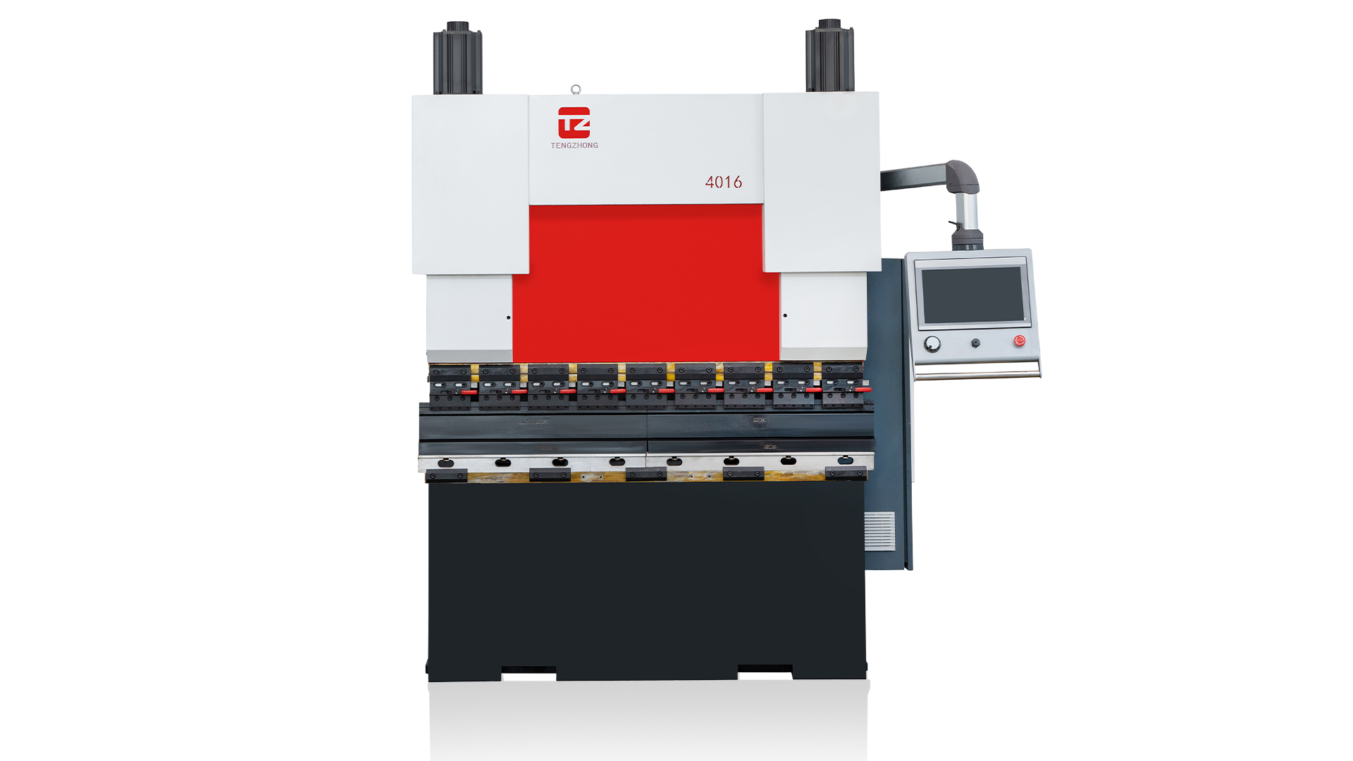
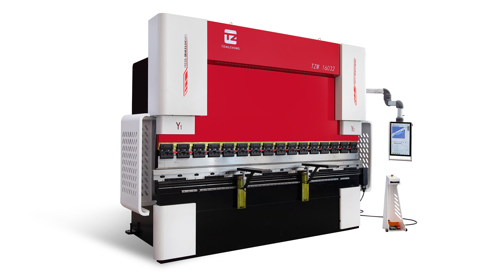
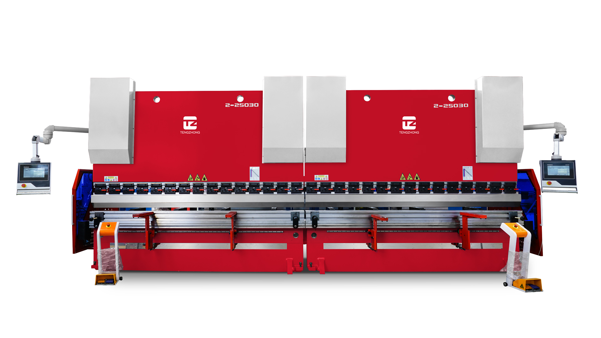
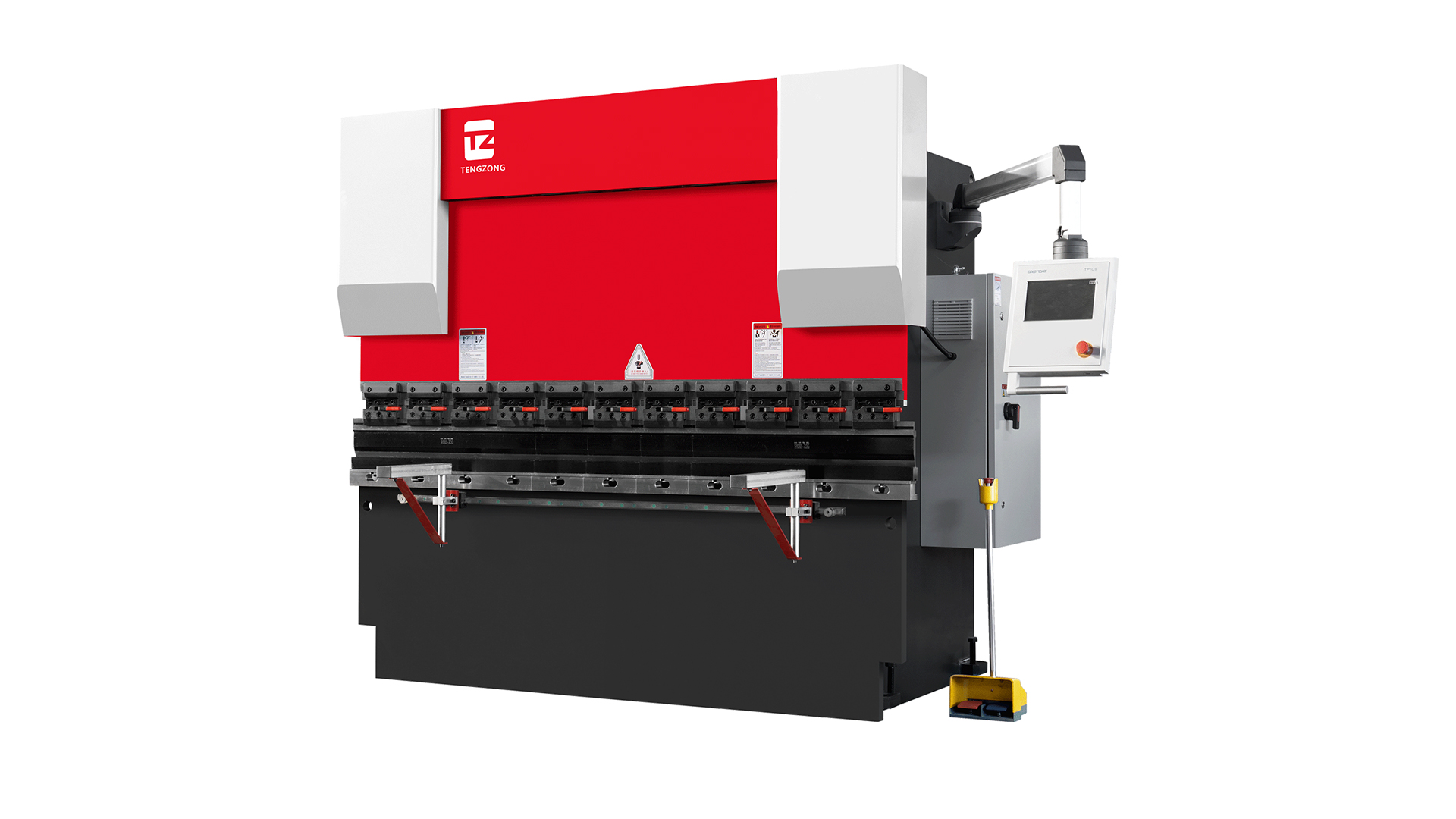
Press Brake Machine: Precision Bending Solutions for Metal Fabrication
2026-07-03
Content
A press brake machine delivers precise, repeatable bends when it is correctly matched to the material type, thickness, and production demands. The right selection and setup directly reduce scrap, shorten cycle times, and improve part consistency across high‑mix or high‑volume fabrication environments.
Press Brake Drive Types and Their Performance Profiles
The drive system defines energy consumption, speed, and achievable bending accuracy. Three primary configurations dominate modern workshops.
- Hydraulic press brakes use synchronized cylinders and offer high tonnage capability, typically up to 3,000 tons or more. They excel in heavy plate bending but run continuously, consuming energy even during idle periods. A standard hydraulic machine bends at approximately 0.4 to 0.6 inches per second.
- Electric servo press brakes employ a belt‑and‑pulley or ballscrew drive powered by a servo motor. They consume power only during the bending stroke, cutting energy use by up to 50% compared to hydraulic equivalents. Bending speeds frequently reach 1.0 to 1.5 inches per second, and repeatability stays within ±0.0004 inches on precision models.
- Hybrid systems combine a servo‑driven pump with a hydraulic cylinder, reducing oil volume and energy consumption while retaining the high‑force advantages. They offer a middle ground, often achieving 0.8 to 1.2 inches per second ram speed with consistent full‑tonnage performance.
| Drive Type | Approach Speed (in/s) | Bending Speed (in/s) | Energy Use (kWh per 1,000 bends) |
|---|---|---|---|
| Hydraulic | 3.2 | 0.5 | 8.4 |
| Electric Servo | 4.7 | 1.3 | 3.9 |
| Hybrid | 4.0 | 1.0 | 5.2 |
Tonnage Calculation and Material Considerations
Applying the correct bending force prevents under‑bending, tool damage, and ram deflection. Air bending tonnage is commonly estimated using the formula: force (tons) = (1.42 × tensile strength (ksi) × thickness² (in) × bend length (ft)) / (die opening (in) × 12). In practice, a reference table built on mild steel values gives faster guidance.
Typical Bending Force for Mild Steel (60,000 psi tensile)
| Material Thickness (in) | Die Opening (in) | Tons per Foot (approx.) |
|---|---|---|
| 0.125 (10 ga) | 1.0 | 8.5 |
| 0.187 (3/16") | 1.5 | 13.0 |
| 0.250 (1/4") | 2.0 | 16.0 |
| 0.375 (3/8") | 3.0 | 22.5 |
Thus, a 10‑foot bend in 1/4‑inch mild steel with a 2‑inch V‑die demands roughly 160 tons. Stainless steel with 75,000 psi tensile strength increases that requirement by about 25%. Always confirm that the machine’s rated tonnage is available at the midpoint of the stroke, not just at bottom dead center.
Tooling Selection for Accurate Bends
Punch and die geometry determines the inside bend radius, springback compensation, and overall profile. Standard 85‑degree punches and V‑dies handle most air bending applications, while acute angle tooling (30–60 degrees) is required for tight radius work.
Die Opening and Minimum Flange Length
Selecting a die opening approximately 8 times the material thickness yields an inside radius close to the thickness. The minimum flange length that can be formed cleanly is about 70% of the die opening. For a 1.5‑inch die, the smallest flange should be at least 1.05 inches, or the workpiece may slip into the die and distort.
Segmented tooling with precision‑ground, quick‑change clamping systems further reduces setup time. A full set of punches and dies in lengths of 1, 2, 4, and 8 inches allows operators to build any required length, slashing changeover to under 5 minutes on modern electric machines.
Control Systems and Backgauge Precision
CNC controllers now offer graphical programming, automatic bend sequence calculation, and real‑time angle correction. A 5‑axis or 6‑axis backgauge positions parts accurately along multiple planes, handling complex profiles without manual repositioning. Backgauge repeatability on high‑end electric press brakes reaches ±0.0002 inches, which directly translates into tighter tolerance stacks on assemblies.
Offline programming software imports 3D CAD files and generates bending simulations, flagging collisions before metal ever touches the machine. Shops that adopt offline programming report up to 30% higher machine utilization because programming happens away from the shop floor, keeping the press brake in production.
Preventive Maintenance and Safety Practices
A structured maintenance schedule protects bending accuracy and extends service life. Key tasks and their recommended frequencies include:
- Daily: Clean the tooling seats, inspect hydraulic oil level and temperature, and verify backgauge finger alignment.
- Weekly: Lubricate guide rails and ball screws, check ram parallelism using a test bend, and cycle safety light curtains.
- Monthly: Replace hydraulic filter elements, examine electrical connections for tightness, and calibrate the Y‑axis position.
- Annually: Conduct a full geometry check, test the pressure relief valve, and replace hydraulic fluid if its viscosity has degraded more than 10% from specification.
Safety systems must include light curtains certified to finger and hand protection resolutions, dual foot pedal or dual palm‑button controls, and mechanical locking of the ram during tool changes. Laser‑based active optoelectronic protective devices, capable of stopping ram movement within 20 milliseconds, have become standard on machines operating at high approach speeds.

-
Phone
+86 131-4173-2687
-
Address
6 Jianghai Road,Libao Town, Haian. Jiangsu Province, China
-
Medla

Copyright o Nantong Tengzhong Machinery Manufacturing Co., Ltd. All Rights Reserved.
