 English
 русский
 Français
 Español
 Português
 عربى
عربى-


Model:
-

Model:
-

Model:
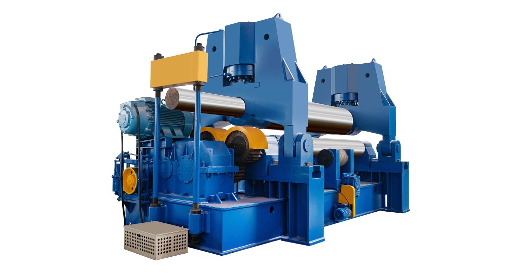
How to Adjust the Roll Gap on a Plate Rolling Machine to Ensure Uniform Bending
2025-10-03
Content
Achieving a perfectly cylindrical or conical shape from a flat steel plate is the primary goal of any plate rolling operation. The most common and frustrating obstacle to this goal is inconsistent bending, resulting in a shape with a flat spot at one end or a pronounced spiral twist. The root cause of these defects almost always lies in an incorrectly set or inconsistently maintained roll gap.
Understanding the “Why”: The Relationship Between Gap and Curvature
Before touching the plate rolling machine, it’s crucial to understand what you are controlling. The roll gap—specifically the distance between the top roll and the bottom rolls—does not directly set the final diameter. Instead, it determines the bend radius imparted to the plate at the point of contact.
A smaller roll gap forces the plate to deform more severely, resulting in a tighter bend radius (a smaller cylinder).
A larger roll gap allows the plate to deform less, resulting in a larger bend radius (a larger cylinder).
For a uniform cylinder, this bend radius must be identical from one edge of the plate to the other. If the gap is wider on the left than the right, the left side will be flatter than the right.
Essential Pre-Adjustment Checklist
Success hinges on preparation. Skipping these steps will make precise gap adjustment impossible.
1. Verify Machine Condition:
Inspection: Check for excessive play or wear in the roll bearings and adjustment mechanisms. Any slop will lead to inconsistency.
Roll Cleanliness: Ensure all rolls are free of dirt, scale, or weld spatter. A small piece of debris can throw off the entire gap setting.
Alignment: Confirm that all rolls are parallel to each other. Misaligned rolls are a primary cause of conical shapes (one end larger than the other).
2. Understand the Material:
Thickness Consistency: Measure the plate thickness at several points, especially near the edges. It is not uncommon for plate stock to have a slight taper (e.g., 19.8mm on one end, 20.2mm on the other). This variation will cause inconsistent bending even with a perfectly set gap.
Material Properties: Be aware of the yield strength of the material. Harder materials will require more pressure (a smaller effective gap) to achieve the same bend radius as softer materials.
3. The Critical First Step: Setting a Theoretical Zero Point
Before loading the plate, you must establish a baseline.
Slowly bring the top roll down until it makes firm contact with both bottom rolls.
This is your “zero point.” The digital readout or mechanical scale should be set to zero at this moment. If your machine lacks this feature, carefully mark the position.
Now, when you raise the top roll to the desired gap (e.g., the plate thickness plus a small clearance), you are starting from a known, repeatable reference.
The Step-by-Step Gap Adjustment Procedure
Follow this methodical process to dial in a uniform gap.
Step 1: The Initial Symmetrical Gap Setting
Calculate your starting gap. A common rule of thumb is to set the top roll gap to 1.1 to 1.3 times the material thickness. For a 20mm plate, you would start with a 22mm gap. This provides enough clearance to feed the plate without excessive force while initiating the pre-bend.
Raise the top roll to this calculated height, ensuring the adjustment is equal on both sides. Use a feeler gauge or a set of calipers to physically measure the gap at both the left and right ends of the rolls. Do not rely solely on the machine’s scale at this stage.
Step 2: The First Pre-Bend and Measurement
Feed the plate into the machine until the lead edge is just past the top roll.
Perform the first pre-bend on both leading and trailing edges. For a initial pinch machine, this means bending one end, then reversing the plate to bend the other.
Do not complete the cylinder yet. Your goal is to create two symmetrical bends at either end.
Step 3: The “Rock Test” and Visual Inspection
This is the most critical diagnostic step.
Place the pre-bent plate on a flat surface or a known-good reference cylinder.
Gently rock the plate. Observe:
Does it rock from side to side? This indicates the bend radius is different on each side—the gap is uneven.
Does it sit flat with a consistent gap underneath? This indicates the bends are symmetrical.
Also, visually assess the gap between the plate and your reference surface. A tapering gap is a clear sign of an inconsistent roll gap.
Step 4: Making Fine-Tuned Corrections
Based on your findings from the Rock Test:
If one side is flatter (has a larger radius): The roll gap was too large on that side. You need to lower the top roll more on that specific side for the next pass. Make adjustments in small increments—0.1mm to 0.2mm at a time.
If one side is tighter (has a smaller radius): The roll gap was too small on that side. You need to raise the top roll slightly on that side.
Important: After each adjustment, you must re-pre-bend the leading edge and perform the Rock Test again. This iterative process is the key to success.
Step 5: Final Rolling and Verification
Once the pre-bent ends are perfectly symmetrical and the plate passes the Rock Test without any rocking, you can proceed to roll the complete cylinder.
Pass the plate through the machine, making gradual adjustments to the top roll to close the circle.
Once rolled, perform a final inspection. The best practice is to use a template or a circumference tape to check for consistency. Weld the seam and then check the cylinder on a rolling table or with a laser scanner for the final confirmation of roundness.
Troubleshooting Common Problems
Barrel Shape (Larger Diameter in the Middle): This is often caused by roll deflection. The massive pressure of bending causes the rolls to bow slightly in the middle, creating a larger effective gap there. The solution is to pre-camber (crown) the top roll slightly to counteract this deflection, if your machine has this feature.
Hourglass Shape (Smaller Diameter in the Middle): This is less common but can be caused by excessive pre-camber on a machine for a thinner plate.
Persistent Spiral/Twist: This is almost always a sign of a significant misalignment between the rolls. The rolls are not parallel, causing the plate to be “walked” through at an angle. This requires a major mechanical correction of the machine itself.
Conclusion: Patience and Process are Key
Adjusting the roll gap for uniform bending is not a single action but a process of measurement, testing, and incremental correction. Rushing the pre-bend stage is the most common error. By understanding the principle of gap control, starting from a verified zero point, and religiously using the Rock Test to guide your fine-tuning, you can consistently produce high-quality, uniform cylinders and cones. The time invested in mastering this fundamental skill pays dividends in reduced rework, less material waste, and superior final products.


-
Phone
+86 131-4173-2687
-
Address
6 Jianghai Road,Libao Town, Haian. Jiangsu Province, China
-
Medla

Copyright o Nantong Tengzhong Machinery Manufacturing Co., Ltd. All Rights Reserved.
